All steel tooling provides the most accurate tolerances. These can vary depending on type of tool construction methods, but generally +/-.002 to +/-.005 can be held. Steel rule tooling also varies with the type of construction method. The most accurate is laser cut board with automated bent rule. Depending on length of rule, tolerances can range from +/-.005 to +/-.015. The longer the rule is, the more variation can be expected.
Steel rule dies that are laid out by hand and jigsaw cut can not be held this tight and will generally vary +/ .030. Holes that are cut using punches will have the same tolerance regardless of die construction method. The industry accepted variation on punch dimensions are as follows:
- Hole diameter—less than 3/4” +/-.002
- Hole diameter—from 3 /4”-15/8 +/-.003
- Hole diameter—greater than 15/8 +/-.005
- Hole position tolerance is again best achieved using laser cutting and automated rule bending.
- Depending on distance between holes +/-.005 to +/-.015 can be expected. If the die is laid out by hand and jigsaw cut, the tolerances could be +/-.010 to +/-.030.
These tolerances are general guidelines and can vary based upon die building equipment and the skills of the die maker.
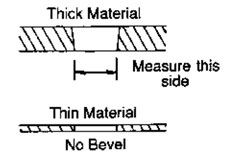 Hole true position can best be determined by coordinate measuring machines. All positional tolerance requirements are to be based upon maximum material conditions (MMC) unless otherwise specified. An example of hole location tolerance for floating fasteners and tolerances for radius with an unlocated center is illustrated at the top of the next page. Hole true position can best be determined by coordinate measuring machines. All positional tolerance requirements are to be based upon maximum material conditions (MMC) unless otherwise specified. An example of hole location tolerance for floating fasteners and tolerances for radius with an unlocated center is illustrated at the top of the next page.
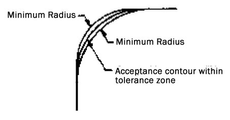
A toleranced radius with an unlocated center creates a tolerance zone defined by arcs tangent to adjacent surfaces within which the part contour must have a faired curve without reversals. The part contour falls entirely within the zone between the minimum radius and the maximum radius, regardless of the actual shape of the part. The radius at all points of the part contour shall neither be smaller than the specified minimum limit nor larger than the maximum limit. See illustration.
To perform their function, gaskets are expected to be compressible and resilient. Materials are often selected for specific applications because of their compressibility. Since the material is intended to be compressed, original thickness and thickness tolerances are important only to the extent that sufficient material remains after compression to fill the gap between flange surfaces. Accordingly, in general, soft compressible materials (sponge, cork) have greater thickness tolerances than firm, less compressible materials (compressed sheet). In no case should these resilient materials be specified with the same thickness tolerances as non-resilient materials such as steel. Typical thickness tolerances for resilient gasketing materials are listed below.

In the previous section “Dimensional Characteristics,” it was suggested that dimensional verification of tooling be made on die impressions rather than on cut gaskets due to the dimensional instability of some materials. This procedure may be acceptable in the fabricator’s workplace but it may not satisfy the needs of the gasket user. Accordingly, attention must be given to the gasket dimensions at the place of application. If the gasket material shows significant dimensional change in changes of atmospheric conditions, the gasket must be protected from these influences. In recognition of this characteristic, gaskets convertd from cork containing materials are generally packaged in polyethylene bags. Although cellulosic materials are subject to dimensional change in varying environmental conditions, some cellulose based materials have been reinforced with inorganic fibers to reduce atmospheric dimensional change. Notwithstanding the above information, there are times when convertd gaskets must be checked for their dimensional conformance to blueprint or application requirements. In order to achieve verifiable and accurate dimensions, consideration must be given to atmospheric conditioning of the gasket. ASTM Standard F104-83, Paragraph 8, details the currently accepted conditioning practices.
Measuring devices available and commonly used by gasket fabricators are:
- Calipers
- Coordinate Measuring Machines
- Durometer Gage - instrument to check hardness of rubber and rubberlike material
- Gage Pins - straight, unflanged pins with specific diameters and extremely close tolerances
- Light Section Microscope
- Metal Hardness Tester-device to determine hardness of steel being convertd
- Micrometers
- Optical Comparators
- Radius Gages - precision ground metal strips with accurate radius machined on each end
- Scales - 6” 12” 18”
- Shadow Graph Machines
- Templates - Soft (thin plastic or mylar) Hard (1/8” to 1/2” thick plastic or mylar with steel pins)
- Tolerance Gauge - Tool for visual pass/fail dimensional inspection.
PART IDENTIFICATION
Some manufacturing operations utilize a multitude of similar gaskets. Accordingly, it is frequently desirable to individually identify different parts by number and/or supplier. This identification provides for:
1) Traceability
2) Inventory Verification
3) Efficient Application
There are a number of identification alternatives which can be arranged. Among them:
1) Rubber Stamp with ink - Part Number and/or Supplier Logo
2) Metal Stamp - No ink - Indent Material with Part Number and/or Supplier Logo
3) Screen Print - Part Number and/or Supplier Logo
4) Tie In Bundles and Tag
5) Package Specific Quantities in Printed Envelopes
6) Shrink Pack Specific Quantities - Label
7) Color Code with Rubber Stamp or Screen Printing
8) Notch Edge of Gasket According to Prearranged Code
NOTE: Special operations may add to cost of gasket.
Lot Traceability System
Gasket manufacturers should establish a system for positive identification and record keeping for use when required by customers. The lot identification number for finished gaskets should provide traceability to major manufacturing operations, inspection, testing, and significant raw materials. The method of lot control and identification should be developed by the gasket manufacturer, consistent with their manufacturing facilities and operations, and should include the elements discussed below.
Lot Identification
The lot identification and lot size should be determined by one of the major manufacturing, testing or inspection operations. Significant raw materials may also be considered for lot size and identification. In continuous operations, it may be necessary to select a specific length of time, such as a shift, one day, one week, etc. to determine lot size. In all cases, the lot number assigned to finished gaskets must provide traceability to major manufacturing operations, inspection and test records and significant raw materials. The gasket supplier should assign only one lot code to a lot, regardless of the number of shipping designations. When successive subdivisions of the lot are necessary, the principal code must be supplemented by additional subordinate codes to identify each of the sublots. Each shipping container must be identified with the principal and subordinate codes. The supplier may ship more than one lot on a pallet, but each container on the pallet must contain parts from only one lot. The packing slip must state the number of containers comprising each lot.
Lot Traceability Control
The gasket supplier must establish a system for identifying lots so that:
- Records indicating inspection or tests results contain the principal and subordinate lot code.
- The final inspection reports are cross-referenced to supporting inspection and test documents and the supplier’s code.
|