|
| Prevention of seal failures through proper design, material selection and maintenance certainly minimizes the risk of failure. Attention to the condition of replaced seals, as well as the equipment performance over time, will result in improved process reliability, reduced operating costs and a safer work environment.
O-ring seals often fail prematurely in applications because of improper design or compound selection. This section is designed to provide the user with examples of common failure modes. By correctly identifying the failure mode, changes in the design or seal material can lead to improved seal performance.
From the end-user’s point of view, a seal can fail in three (3) general ways:
- Leaking
- Contamination
- Change in Appearance
|
|
| One major factor in possible seal failure is the extreme and harsh environment in which seals are expected to perform. The sealing environment can consist of virtually anything from inert gases at room temperatures to aggressive chemicals at very high temperatures. The sealing environment may result in chemical degradation or swelling of the sealing components. Elevated temperatures may cause seal degradation, swelling or outgassing. And the pressure—or more often, the vacuum environments—can cause outgassing and weight loss.
Contributing factors to seal failure in the sealing environment include:
- Chemical— the type of chemical(s) in service
- Thermal— the operating ranges of the seal (also any thermal cycling)
- Pressure/Vacuum— the range of pressures or vacuum levels in the process
|
|
| Analysis of the seal application is crucial to the understanding of possible failure. Most seal design is performed by component suppliers and equipment manufacturers. The designs are refined as experience is gained. As quickly as process technology changes, however, the experience gained with seal design may not be relevant to the latest process technology. Vacuum applications have historically relied on high levels of compression and gland fill to reduce permeation and trapped gases. These techniques, when applied to new materials, or at higher operating temperatures, can result in premature seal failure.
The seal design and application can provide information about the cause of failure:
- Static Seals— axial and radial, confined or unconfined
- Dynamic Seals— axial (open-close) or radial (reciprocating or rotary)
- Sealing Gland Dimensions—
- shape (square, trapezoidal, etc.)
- compression
- gland fill
- stretch
- Installation Procedures— stretch
|
|
|
 |
| Description: The seal or parts of the seal exhibit a flat surface parallel to the direction or motion. Loose particles and scrapes may be found on the seal surface. |
|
| Contributing Factors: Rough sealing surfaces. Excessive temperature. Process environment containing abrasive particles. Dynamic motion. Poor elastomer surface finish. |
|
| Suggested Solutions: Use recommended gland surface finishes. Consider internally lubed elastomers. Eliminate abrasive components. |
|
|
|
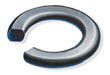 |
| Description: The seal exhibits a flat-sided cross-section, the flat sides correspoding to the mating seal surfaces. |
|
| Contributing Factors: Excessive compression. Excessive temperature. Incompletely cured elastomer. Elastomer with high compression set. Excessive volume swell in chemical. |
|
| Suggested Solutions: Low compression set elastomer. Proper gland design for the specific elastomer. Confirm material compatibility. |
|
|
|
 |
| Description: The seal may exhibit many signs of degradation including blisters, cracks, voids or discoloration. In some cases, the degradation is observable only by measurement of physical properties. |
|
| Contributing Factors: Contributing Factors: Incompatibility with the chemical and/or thermal environment. |
|
| Suggested Solutions: Selection of more chemically resistant elastomer. |
|
|
|
 |
| Description: The seal exhibits blisters, pits or pocks on its surface. Absorption of gas at high pressure and the subsequent rapid decrease in pressure. The absorbed gas blisters and ruptures the elastomer surface as the pressure is rapidly removed. |
|
| Contributing Factors: Rapid pressure changes. Low-modulus/hardness elastomer. |
|
| Suggested Solutions: Higher-modulus/hardness elastomer. Slower decompression (release of pressure). |
|
|
|
 |
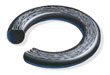
| Description: The seal develops ragged edges (generally on the low-pressure side) which appear tattered. |
|
| Contributing Factors: Excessive clearances. Excessive pressure. Low-modulus/hardness elastomer. Excessive gland fill. Irregular clearance gaps. Sharp gland edges. Improper sizing. |
|
| Suggested Solutions: Decrease clearances. Higher-modulus/hard-ness elastomer. Proper gland design. Use of polymer backup rings. |
|
|
|
 |
| Description: The seal or parts of the seal may exhibit small cuts, nicks or gashes. |
|
| Contributing Factors: Sharp edges on glands or components. Improper sizing of elastomer. Low-modulus/hardness elastomer. Elastomer surface contamination. |
|
| Suggested Solutions: Remove all sharp edges. Proper gland design. Proper elastomer sizing. Higher-modulus/hardness elastomer. |
|
|
|
 |
| Description: This failure is often very difficult to detect from examination of the seal. The seal may exhibit a decrease in cross-sectional size. |
|
| Contributing Factors: Improper or improperly cured elastomer. High vacuum levels. Low hardness/plasticized elastomer. |
|
| Suggested Solutions: Avoid plasticized elastomers. Ensure all seals are properly post-cured to minimize outgassing. |
|
|
|
 |
| Description: The seal exhibits parallel flat surfaces (corresponding to the contact areas) and may develop circumferential splits within the flattened surfaces. |
|
| Contributing Factors: Improper design—failure to account for thermal or chemical volume changes, or excessive compression. |
|
| Suggested Solutions: Gland design should take into account material responses to chemical and thermal environments. |
|
|
|
 |
| Description: The seal often exhibits discoloration, as well as powdered residue on the surface and possible erosion of elastomer in the exposed areas. |
|
| Contributing Factors: Chemical reactivity of the plasma. Ion bombardment (sputtering). Electron bombardment (heating). Improper gland design. Incompatible seal material. |
|
| Suggested Solutions: Plasma-compatible elastomer and compound. Minimize exposed area. Examine gland design. |
|
|
|
 |
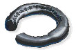
| Description: The seal exhibits cuts or marks which spiral around its circumference. |
|
| Contributing Factors: Difficult or tight installation (static). Slow reciprocating speed. Low-modulus/hardness elastomer. Irregular O-ring surface finish (including excessive parting line). Excessive gland width. Irregular or rough gland surface finish. Inadequate lubrication. |
|
| Suggested Solutions: Correct installation procedures. Higher-modulus elastomer. Internally-lubed elastomers. Proper gland design. Gland surface finish of 8–16 microinch RMS. Possible use of polymer backup rings. |
|
|
|
 |
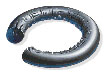
| Description: The seal may exhibit radial cracks located on the highest temperature surfaces. In addition, certain elastomers may exhibit signs of softening—a shiny surface as a result of excessive temperatures. |
|
| Contributing Factors: Elastomer thermal properties. Excessive temperature excursions or cycling. |
|
| Suggested Solutions: Selection of an elastomer with improved thermal stability. Evaluation of the possibility of cooling sealing surfaces. |
|